Therefore I dedicated it a special page on this site.
Simplicity and minimalism that characterized the model is the secret of beauty and reason to fall in love with it.
The model was manufactured in 1968-1970. Based on Type R1123 (same model of "lime").
The model manufactured by SINPAR that also made the Renault 4 4X4. Renault has provided all the parts and plans for the transformation of the saloon to open model.
Probably there were more than 500 cars produced (no exact documentation). The original vehicles had a round SINPAR serial number plate next to the Renault diamond plate.
Because in Israel it is forbidden to make any body alterations by law. And there is no way to transform R4 to PLEIN AIR. We can only enjoy the simplicity of the modification plans:
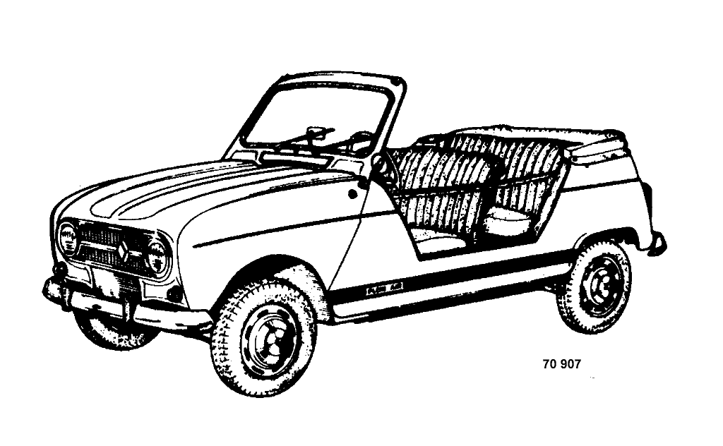
The Renault 4 PLEIN AIR, derived from the R.1123, differs from
the saloon due to body alterations.
These alterations consist principally of:
- modification to the top part of the windscreen.
- addition of side panels ensuring a rigid connection between the
front pillars and the rear because of the absence of doors
- the cutting away of the two rear quarter light panels and the tailgate.
- the fitting of a soft top.
the addition of reinforcing pieces and connecting gussets,
spot welded or gas welded together, gives this assembly sufficient
rigidity to prevent possible distortion arising from hard use.
Description of the various components concerned in the body transformation.
This drawing shows the main bodywork parts available from C.S.S (see PR.903 pages 81-82). Some strengthening pieces or connecting gussets will be made locally.
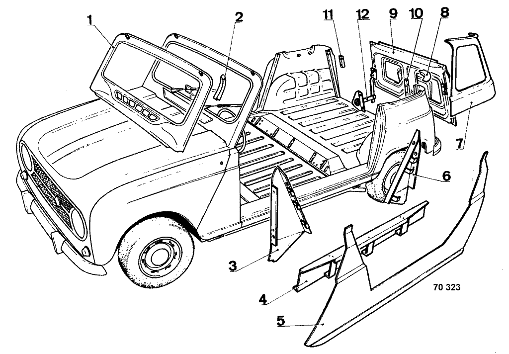
2. Windscreen reinforcement
3.Scuttle reinforcement
4. Side member
5. Side panel
6. Rear reinforcement
7. Quarter light panel (spare part not supplied by C.S.S. refer to PR.808)
8. Half moon closure plate
9. Tailgate
10 and 11. Tailgate stay bracket
12. Hinge assembly.
Windscreen frame
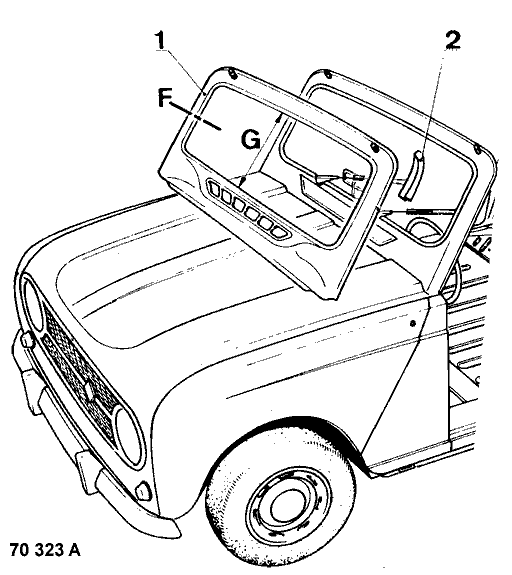 This component is to be replaced when distortion warrants it.
In order to limit the amount of dismantling work it is best to partially replace it by cutting in the areas (F) on the side pillars.
This work must be particularly strong and neatly done as the absence of the roof panel slightly reduces the rigidity of the frame.
When fitting the new component (1) make sure of correct spacing between the upper and lower portions (G) to ensure correct fitting of the windscreen.
The gas welded joints will be covered with plastic filler + hardener.
Note at the same time that the two side reinforcements (2) are available from the C.S.S. where the repair is less serious.
How to fix the reinforcement
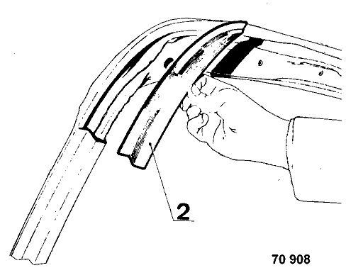
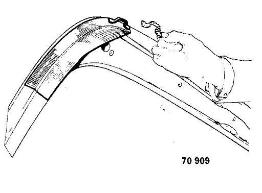
Fitting the reinforcement (2) after cutting out the inside of the windscreen frame upper part.
Then gas weld together.
The fitting of these components has lead to :
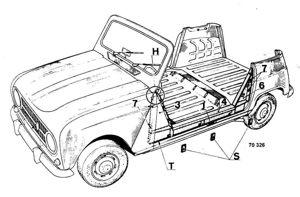
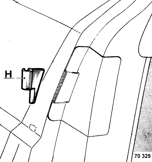 - cutting out the top hinge (H) and the center pillar level with the floor (J).
- the fixing of the front and rear reinforcements (6) is made by hexagonal headed self tapping screws.
- the side member (4) is held in position along its lower edge by the unions of three securing screws inside on the body sill.
- the 3 components (reinforcements and side member) are spot welded together (L).
- modification to wiring harness location.
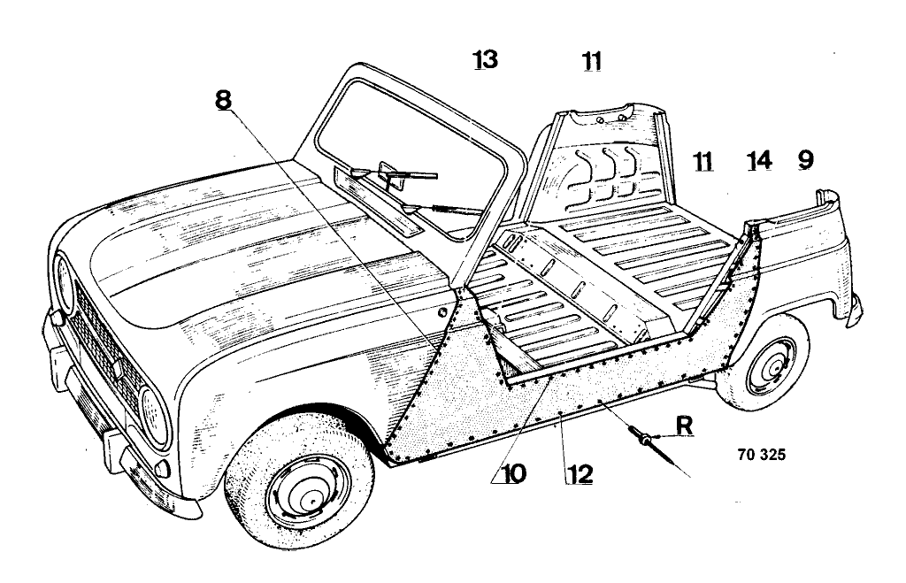
at (8) on the scuttle panel
at (9) on the quarter light panel and the rear wing
at (10) on the top edge of the side member
at (11) on the filler piece brackets.
Only the lower part (12) is fitted by rivets (R) on the body side.
Method for repairing
Depending on the damage, the complete or part replacement of the body side can be undertaken.
Completely replacing
- Remove the mouldings, secured by rivets.
- Unstitch the spot welds and remove the rivets (R) round the body side.
This unstitching can be done by means of a chisel or by drilling with a flat ended drill
(see Use of small tools; MR.61 chapter Bodywork).
- Level off or grind the spot welds on the components remaining in position and protect them with a coating of zinc based paint.
- Offer up the new component holding it in place by body clamps or vice grips.
Spot weld and rivet to the side of the chassis (12).
- Joint (13) and (14) will be brazed.
- The welding seams will be smoothed out by using plastic filler + hardener.
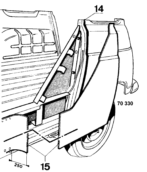 Replacing part of the front or rear can be carried out as follows:
(For example the rear part).
- Unstitch the damaged section up to about 250 mm (9-7/8") beyond the point where the cut out will be made (15).
- Offer up the new component taken from a complete new side panel (from the C.S.S.).
- Mark it off, cut it out and temporarily place in position.
Cross section A-A

5 mm (3/16")
1.5 mm (1/16")
- Fit the two components end to end gas welding points about every 25 mm (1").
- Level off the welding, then complete it in stages, that is to say:
- Weld along about 50 mm (2"), level off.
- Weld along another 50 mm (2") level off etc.
Carry on in this manner, until the two parts are joined.
The aim of this method is to restrict distortion due to heat and make the levelling off easier.
IMPORTANT -
While carrying this out make sure frequently that the new component remains correctly positioned by temporarily securing it.
The surface finish will be obtained by plastic filler + hardener.
Tinning is not recommended (distortion risk due to heat).
Replacing front or rear reinforcements
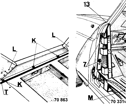 With the side panel removed, lift out the reinforcements by removing the securing screws on the front and rear pillars and unstitch the spot weld (L) on the side member.
When replacing make sure that the side member and the front and the rear pillars which act as a base are not distorted.
Prepare the front pillar by drilling two holes for the fixing the reinforcement.
Bolt the reinforcements on using bolts (7) making sure that they are correctly in position.
Spot weld together at (L).
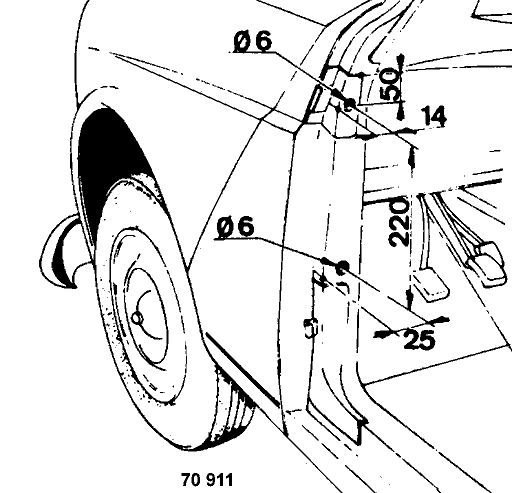 This component which is spot welded to both reinforcements can be taken off by removing the front and rear pillar securing bolts together with the three securing bolts on the body sill.
On the left side be careful not to damage the wiring harness (M).
When refitting do not forget the anti-drumming felts (S) on the stiffener sides and carry out sealing between the side member and the chassis section using two wide strips of mastic 297 sealing compound.
220 mm (8-11/16")
50 mm (1-15/16")
14 mm (9/16")
25 mm (1")
Diameter 6 mm (1/4")
-----------------------------------------------------------------
There are two possible methods for repairing a rear quarter panel.
In both cases, the parts must be completely or partly cut out from the components available from C.S.S. (see PR.808).
Only replacement of the upper part of the rear quarter panel is shown here.
For a bigger repair requiring wheel house replacement refer to MR.103 section M-010 "Accident Damage".
Method of operation
Partially replacing (+ tailgate pillar).
Where only the rear part is damaged partial replacement is advised, carrying out as follows
- Reform to approximately the pre-accident shape.
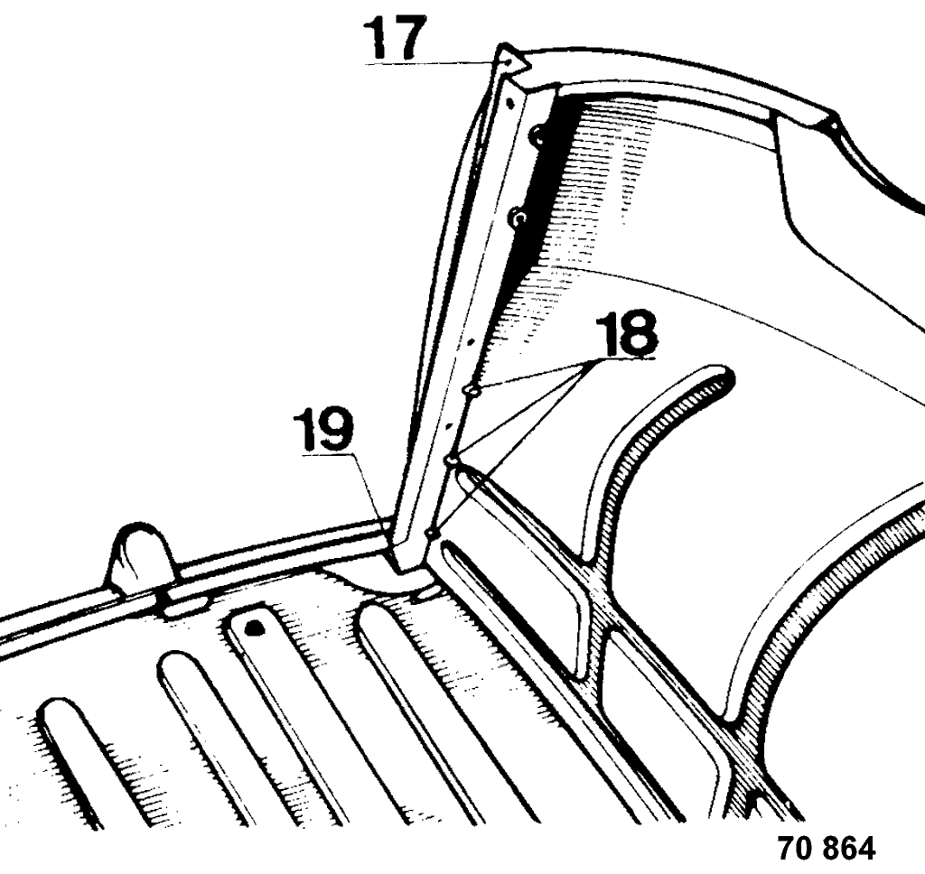
- Remove the rear wing securing bolts (16) and detach the rear wing carefully (arrow), the front part remaining covered by the side panel (P).
- Unstitch the spot welds at the joint between the wheel house and the rear pillar connecting panel (17).
- Cut out the damaged section following the line chosen (U).
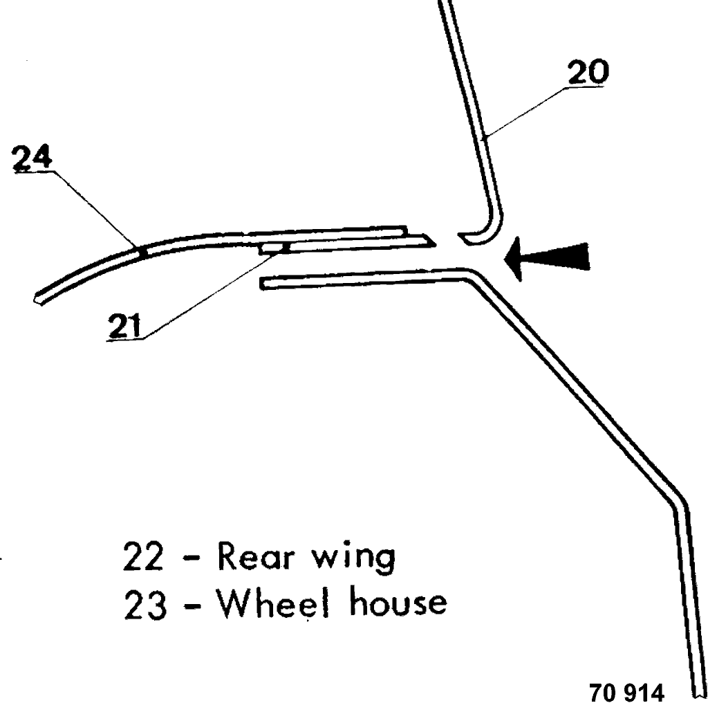
- At the bottom of the panel level off the welding seam (21) remaining in place.
- Level off and clean the part to be welded.
- Mark off and cut, in the new parts, the replacement sections required (quarter panel and tailgate frame).
- Offer up these parts using the tailgate door as a jig.
- Weld together the the joint between:
the wheel house and the tailgate frame (17) by spot welding.
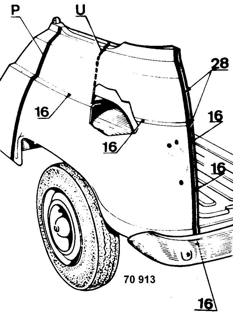
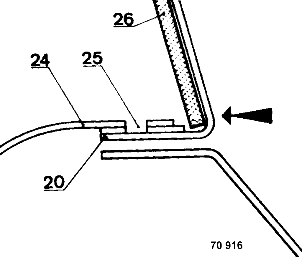
The bottom face of the panel (20) covers the wheel house (24).
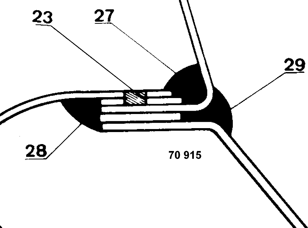
Before fitting this panel, drill several holes (25) in order to fit the two components (23), take care to cover the rear quarter panel with a sheet of asbestos (26).
- Gas weld the panels (U) together, if necessary level off and cover with plastic filler.
- Ensure sealing by a wide strip of mastic 297 sealing compound placed after fitting the rear wing at (27) and (28).
The outside joint (29) will be covered by a strip of mastic 307 sealing compound.
- Refit the moulding.
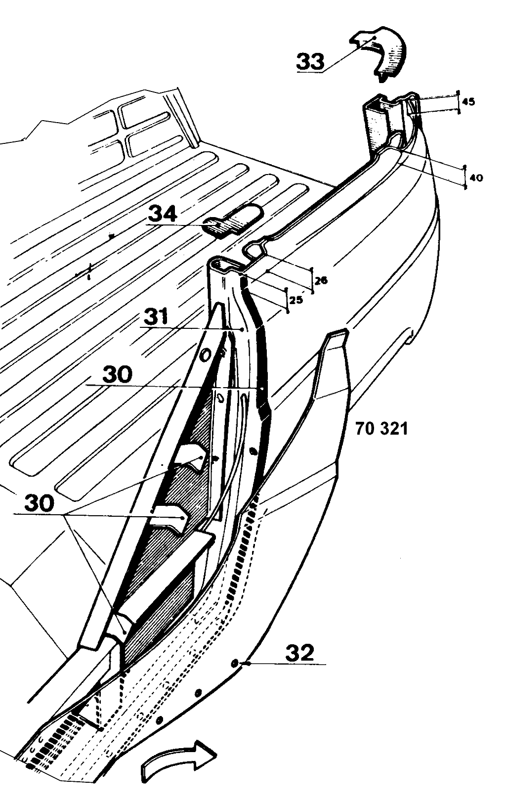
25 mm = (1")
26 mm = (1-1/16")
40 mm = (1-9/16")
45 mm = (1-3/4")
This operation is similar to the preceding one with the addition of partial removal of the side panel.
Method of operation
- Unstitch the spot welds on the side panel and on the brackets (30).
- Remove the rivets (32) along the bottom.
- Lift the side panel gently without distorting it (arrow).
- Cut out the blanking piece (34) on the rear pillar and then remove the hood frame hinge.
- Unstitch the spot welds on the rear pillar (31).
For a larger repair replace the pillar (see operating in MR.103, section M-010 "Accident Damage").
When refitting, offer up the new components, and hold in place by tack brazing.
- Check that their position is correct by making sure that the measurement between the right and the left hand hinges is 1,204 mm (51-5/16") and using the tailgate as a jig 905 mm (35-5/8").
- Spot weld the rear pillar and the tailgate frame together for good.
- Fit the tailgate reinforcement (35) in place.
- Weld the half moon closure plate (33).
- Fit the blanking plate (34) and the hood frame hinge (plate (34) is to be made locally to the drawing overleaf).
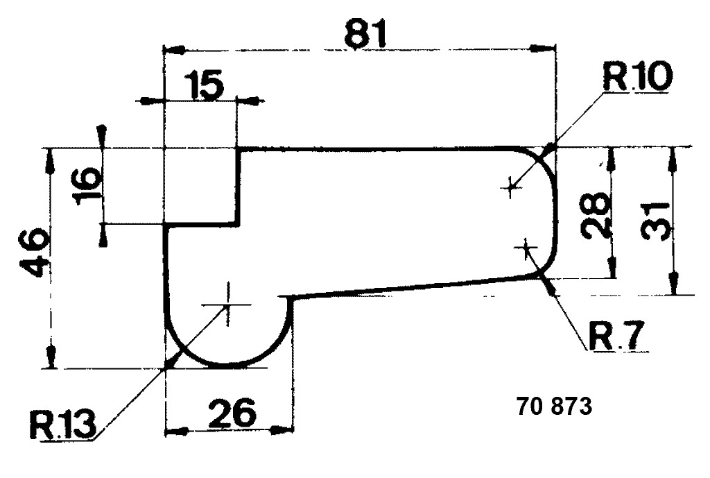 81 mm = (3-3/16")
15 mm = (9/16")
16 mm = (5/8")
46 mm = (1-13/16")
26 mm = (1-1/16")
28 mm = (1-1/8")
31 mm = (1-1/4")
10 mm = (3/8")
13 mm = (1/2")
7 mm = (1/4")
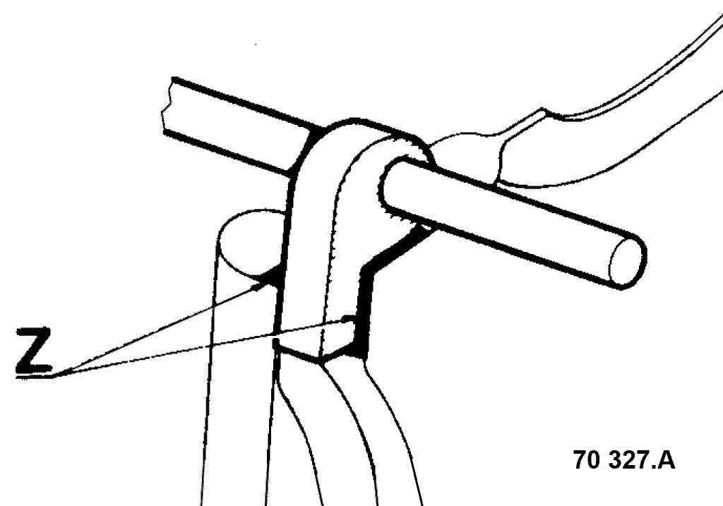
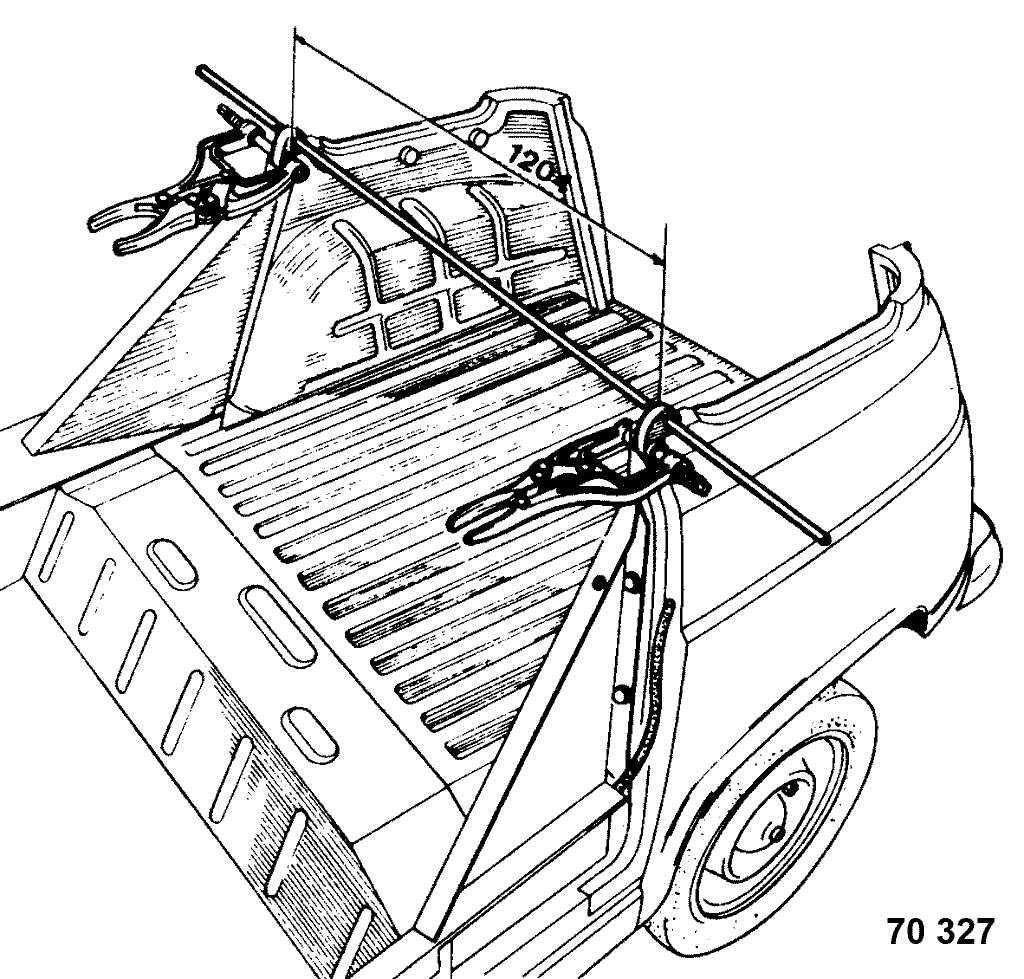
1204 mm (47-3/8").
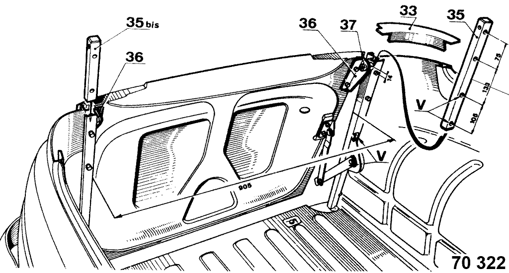
75 mm = (2-15/16")
133 mm = (5-1/4")
105 mm = (4-1/8")
14 mm = (9/16")
905 mm = (35-5/8")
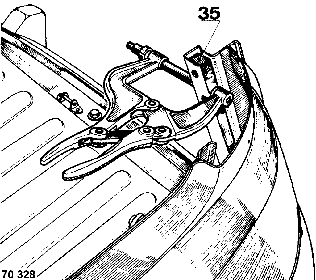
Available as a special spare part component this door is hinged using two hinges screwed on to the door frame.
The hinge pins (37), secured by female Allen screws, screw into the reinforcements (35) and (35 bis).
When replacing a tailgate frame arrange to fit the hinge reinforcements counter-balance before welding the closure panels (33).
The counter-balance fitting is further down by comparison with that on the saloon (holes (V)).